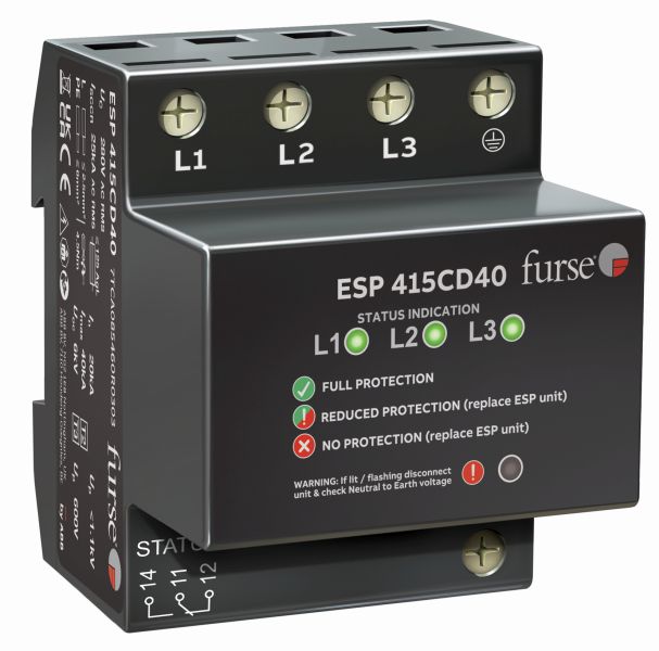
The ESP 415CD40 is a combined Type 2 and 3 tested (to BS EN 61643) Surge Protective Device (SPD) for use on three-phase mains power distribution systems primarily to protect connected electronic equipment from transient overvoltages on the mains supply, e.g. computer, communications or control equipment.
For use at boundaries up to LPZ 1 through to LPZ 3 to protect sensitive electronic equipment.
Features & Benefits
- Very low let-through voltage (enhanced protection to BS EN 62305) between all sets of conductors (phase to neutral, phase to earth, neutral to earth – Full Mode protection).
- Protector includes a hybrid combination of MOVs and GDTs.
- Innovative multiple thermal disconnect technology for safe disconnection from faulty or abnormal supplies (without compromising protective performance).
- Three-way visual indication of protection status and advanced pre-failure warning so you need never be unprotected.
- Changeover active volt-free contact enables the protector to be used to warn of phase loss (i.e. power failure, blown fuses etc).
- Compact space-saving DIN housing with DIN release and locking feature for easy positioning onto DIN rail.
- Innovative design delivers zero leakage current to earth, so is suitable for TT and TN earthing systems.
Application
Install on three-phase supplies at final distribution board level to protect electronic equipment against transient overvoltages.
Installation
Install in parallel, within the power distribution board or directly (via fuses) onto the supply feeding equipment.
At distribution boards, the protector can be installed either on the load side of the incoming isolator or the closest outgoing way to the incoming supply.
Connect, with very short connecting leads, to phase(s), neutral and earth.
Specifications
- Nominal voltage – Phase-Neutral Uo (RMS) 240 V
- Maximum voltage – Phase-Neutral Uc (RMS) 280 V
- Temporary Overvoltage TOV UT(1) 350 V
- Short circuit withstand capability 25 kA/50 Hz
- Working voltage (RMS) 346-484 V
- Frequency range 47-63 Hz
- Max. backup fuse (see installation instructions) 125 A, parallel connection via series fuses to supply – see installation guide
- Leakage current (to earth) Zero
- Indicator circuit current < 10 mA (per phase, to neutral)
- Volt free contact:(2) Screw terminal
- Current rating 1 A
- Nominal voltage (RMS) 250 V
- Temperature range -40 to +80 °C
- Connection type Screw terminal
- Conductor size (stranded) 35 mm2 (solid), 25 mm2 (stranded) – maximum torque 4.5 Nm
- Earth connection Screw terminal
- Volt-free contact Connect via screw terminal with conductor up to 1.5 mm2 (stranded) – maximum torque 0.25 Nm
- Degree of protection (IEC 60529) IP20
- Case material FR Polymer UL-94 V-0
- Weight: – Unit 0.4 kg
- Weight: – Packaged 0.5 kg
- Dimensions to DIN 43880 – HxDxW(6) 90 mm x 88 mm x 72 mm (4TE)
-
CN8: 8536308000

