
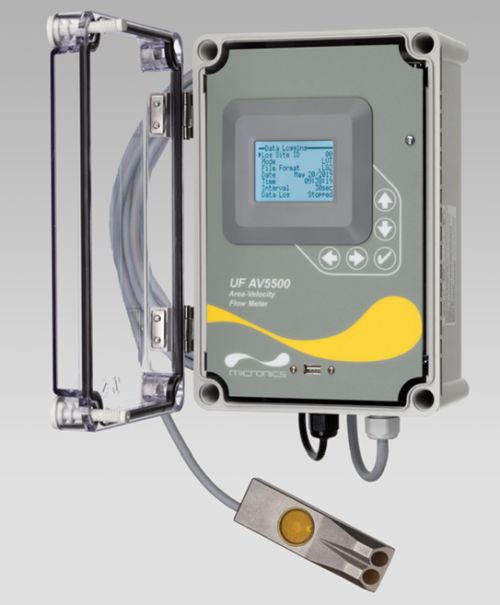
The UF AV5500 Area-Velocity Flow Meter includes a submerged ultrasonic sensor installed at the bottom of an open pipe or channel. Exposed materials are stainless steel, so the sensor resists fouling and corrosion. It has no moving parts and no orifices, ports or electrodes.
Features
- Measure flow in pipes and open channels of any shape.
- Auto-detects the field installation of options, serial communications, and control relays.
The UF AV5500 displays and totalises flow. It includes three 4-20mA outputs (Flow, Level and Velocity), plus two control relays for level alarms or flow proportionate pulse output for samplers and chlorinators. It is easy to calibrate with the built-in keypad and menu system. A built-in 26 million point data logger with USB output is standard. Intrinsic Safety Barriers for sensor and cable installation in hazardous-rated channels are also optional.
Recommended for:
- Wastewater
- Industrial Effluent
- Stormwater
- Combined Sewers
- Natural Streams
- Irrigation Water
Area-Velocity Flow Meter
Measure flow through open channels, partially full pipes and surcharged pipes without a flume or weir. Ideal for wastewater, stormwater, effluent, industrial wastewater and irrigation water.
Submersible Ultrasonic Sensor
The Micronics UF AV5500 uses a submerged ultrasonic sensor to continuously measure both Velocity and Level in the channel. The sensor resists fouling, corrosion and abrasion. The flow meter can be configured with the standard submerged velocity-level sensor, or with submerged velocity plus a separate non-contacting ultrasonic level sensor, for highly aerated fluids or those with a high concentration of suspended solids.
View flow rate and total flow on the large backlit LCD display and connect to external devices with three 4- 20mA outputs and two control relays. Flow rate, volume, run hours, and diagnostic information are available through the optional Modbus RTU serial communications.
Easy to Use
The UF AV5500 Area-Velocity Flow Meter measures both Level and Velocity to calculate flow in an open channel or pipe. Configuration is simple: enter the pipe diameter or channel dimensions, and the UF AV5500 automatically computes and displays flow volume.
The ultrasonic sensor mounts inside the pipe or on the bottom of a channel with a stainless steel mounting bracket (included) and a single screw into the bottom of the pipe or channel. No special compounds, tools or hardware are required. The sensor is completely sealed with no orifices or ports.
Recommended Pipe or Channel Conditions
Careful selection of sensor mounting location results in the best performance and maintenance-free operation. Avoid locations where sediment builds up.
The best possible accuracy will result when the water is not highly turbulent and the velocity is evenly distributed across the channel. The channel should not have drops or direction changes immediately upstream of the sensor mounting location. Pipe or channel slope should not exceed 3%. See the installation manual for specific installation recommendations.
The UF AV5500 can measure forward flow velocity up to 6 m/sec (20 ft./sec) and reverse flow up to 1.5 m/sec (5 ft./sec). The electronics and software sample and average flow rates continuously to provide stable readings. The submerged velocity/level sensor will measure flow in partially full and surcharged pipes with pressure up to 10 psi. No special set-up or adjustment
is required. Minimum recommended pipe diameter is 150 mm (6″).
Alternate Sensor Configurations
Alternate sensor models are available for special applications, such as a separate non-contacting ultrasonic level sensor with a submerged velocity sensor. Sensor cable can be extended up to 150 m (500 ft.). Use this configuration for pipes or channels with a high concentration of air or suspended solids.
Custom Channel Shapes
Configure the UF AV5500 for installation in irregular or compound channel shapes by entering the channel width at multiple level points through a simple menu.
Channels of virtually any shape can be monitored with your choice of measurement units.
Standard 26 Million Point Data Logger
The UF AV5500 will store time and date-stamped flow values at 10-second to 60-minute intervals.
Daily flow reports are automatically created, and total, minimum, maximum, and average flow rates are displayed on the LCD display. Transfer log files and daily flow reports to any USB flash drive by connecting to the logger’s USB output. Windows software is included to display log files in graph and table formats, change measurement units and generate flow reports. Or download data in a .csv file format to import directly into Microsoft Excel.